Planar Doppler Velocimetry
Planar Doppler Velocimetry
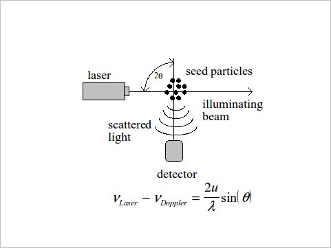
Planar Doppler Velocimetry (PDV, also known as Doppler Global Velocimetry, DGV) is an image-based technique that is capable of producing three component velocity measurements in a plane. With PDV, one measures the Doppler shift of light scattered by seed particles in the flow, similar to LDV. To perform PDV, the flow is seeded with scattering particles and a laser sheet is used to illuminate the interrogation region. The interrogation region is imaged through molecular absorption filters by several CCD cameras and the images are post-processed using a set of calibration images to determine velocities.
With PDV, one measures the Doppler shift of light scattered by seed particles in the flow, similar to LDV. The Doppler shift is dependent on the incident light wavelength, the velocity of the scattering particle, and the observation and incident light directions. With LDV, the Doppler shift is determined using heterodyne detection of the beat frequency between the incident and scattered (Doppler shifted) light. For PDV, a molecular or atomic vapor filter is used as the frequency discriminator.
One of the key advantages of PDV is that it is not necessary to image and track individual particles, as is the case with Particle Image Velocimetry (PIV). In fact it is desirable to collect scattering from numerous particles at each pixel. These relaxed imaging requirements facilitate interrogation of large fields of view, operation at large distances from the laser sheet, or utilization of small seed particles (sub-micron). Generally, PDV requires more cameras and more extensive calibration procedures than PIV. The technique is still being developed and tested by several teams including (University of Illinois, DLR, and NASA), a brief overview is given here.
The basis of PDV is the use of the atomic or molecular vapor filter as a frequency discriminator. A laser with a narrow (~ 100-MHz) linewidth is tuned to one edge of a molecular or atomic absorption line. The scattered light, which has been Doppler shifted, is imaged or detected through the molecular or atomic absorption filter. The sharp transmission-versus-frequency edge allows the filter acts as a frequency discriminator by converting changes in frequency (Doppler shift) to changes in intensity. The scattered light can be detected using a point detector (photo-multiplier or photo-diode) or a camera and converted to velocity.
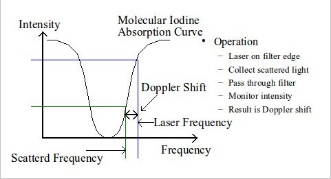
One common implementation of the PDV system employs a seeded Nd:Yag laser (532-nm) and a molecular Iodine filter. The spectrum of molecular Iodine includes discreet rotational and vibration bands with very fine structure in the visible (490-650 nm) spectrum. For this reason, Iodine has been used as a spectral frequency references for many years. For the purposes of PDV, the laser is tuned to a point near a strong isolated line (for example ~ 18789.25 cm-1). The depth of the absorption lines can be adjusted by changing the number density of the Iodine in the cell.
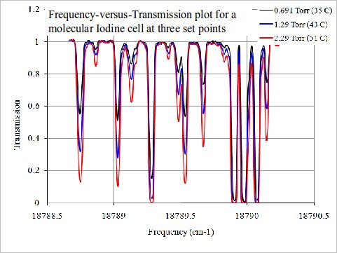
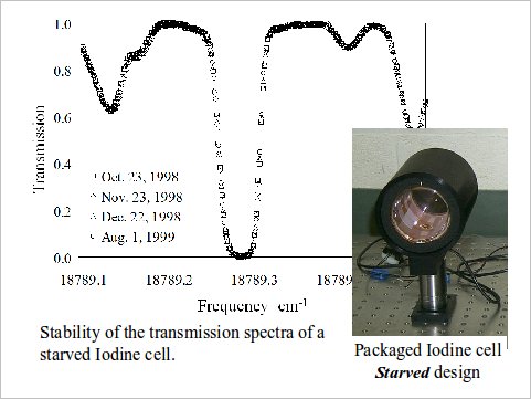
The stability of the Iodine cell transmission-vs-frequency profile has been identified as a significant source of error for PDV systems. This instability is caused by variations in the vapor pressure of Iodine in the cell (number density). Iodine vapor is a strong function of temperature, and therefore, small changes in cell temperature (~ 0.1 °C) can have significant impact on the transmission-vs-frequency profile. One way to resolve this issue is to operate the cell in a starved or super heated vapor mode and then seal the cell permanently. To create the permanently sealed starved cell, the cell is evacuated and cold-finger filled with Iodine is brought to the desired vapor pressure (cold-finger operating temperature). The stem between the cold-finger and cell is then permanently sealed with a torch, isolating the Iodine in the cell body and fixing the number density. The cell is then operated 10-20 °C above the cold-finger set temperature and the Iodine in the cell is a super-heated vapor with a set number density. The result is a molecular cell with a very stable absorption spectra.
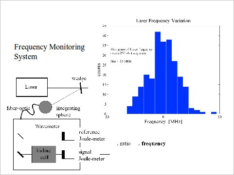
Another source of error is shot-to-shot variations in the laser frequency (wavelength). As the basis of PDV is to measure frequency changes in the scattered light caused by Doppler shifts, any variation in the operating frequency of the laser will be manifest as an error in velocity. The solution to this problem is to monitor the laser frequency and correct the Doppler shift data using this information. The frequency of the laser can be monitored shot-to-shot by passing a small portion of the laser pulse through an Iodine cell and converting the measured intensity to frequency using the Iodine cell transmission-vs-frequency profile. This setup is called a frequency monitoring system or wavemeter.
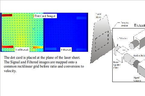
It is not reasonable to assume that the flow is seeded uniformly or that the laser power is constant and uniform over the field of view. These variations in seeding or laser power will result in changes in the intensity measurement, and therefore, errors in velocity if they are not corrected. To eliminate these variations, a reference or unfiltered image is used to normalize the filtered image. This process introduces several processing procedures such as alignment of the filtered and unfiltered images which were acquired using tow cameras and correcting for non-uniform gain from pixel to pixel on each camera.
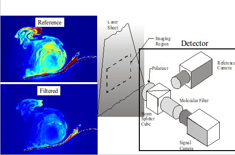
Image alignment is simplified by using a non-polarizing beam splitter and imaging a rectilinear grid at the plane of the laser sheet. This image, called a dot card, is then used to perform a linear mapping of the bitmap images onto a rectilinear grid for post processing. Using identical cameras with identical lenses and imaging through the beam splitting cube minimizes optical distortions and therefore the image alignment procedure can be accomplished with a bi-linear interpolation.
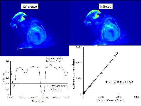
Compensation for variations in camera response is accomplished by tuning the laser to a flat portion of the Iodine transmission-versus-frequency curve and acquiring images over a wide range of intensities. Setting the laser to a flat portion of the curve means that the intensity of the Doppler shifted light is not modified by the Iodine transmission curve and therefore, the scattered light detected by the Filtered and Reference cameras should be identical. These images, called green cards, are then used to produce a pixel-by-pixel plot of the gain of the filtered camera (S2) versus the gain of the reference (S1) camera. This curve, which is generally very linear, is then used to normalize the filtered/unfiltered camera ratio at each pixel. An example of the curve fit at a single pixel is shown here.
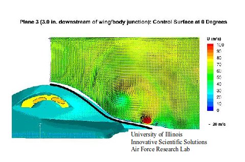
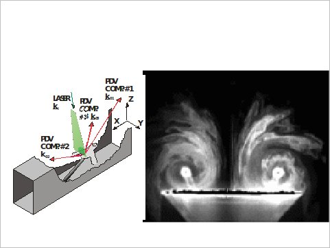
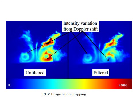
An example of the PDV data acquisition process on a simple delta wing in the SARL is shown here. Raw PDV images from a filtered and unfiltered camera show the intensity variations from the laser sheet and seed. A close examination of the filtered and unfiltered image shows the effect of the filter on the data. The signal from each vortex is relatively uniform around each vortex in the unfiltered image. In the filtered image the intensity is noticeably lower at the top of the vortex on the left and the bottom of the vortex on the right. This is due to Doppler shifts of the scattered light.
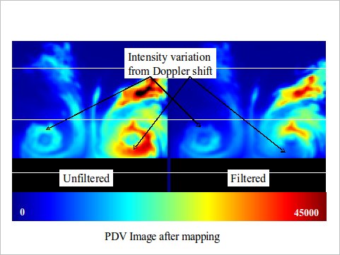
The ratio of the de-warped images is computed and converted to frequency using the Iodine cell calibration and data from the frequency monitoring system. The Doppler shift data from three independent views can then be combined and converted to three component velocity vectors.
PDV Hardware
For ordering information please contact our sales department: [email protected] or call us at (937) 630-3012
For technical support, please contact our support department: [email protected] or call us at (937) 630-3012
2026 © Innovative Scientific Solutions, Inc.